SwiftPro Drone Setup Guide
Overview
Step 1: Choose Firmware Type
If we want to fly drone in FlowHold Mode.
| Feature | ArduPilot Standard Stable Version | ArduPilot Custom Version |
|---|---|---|
| Flowhold Mode | Not available | Available |
Step 2: Choose Flight Controller Type
Select the appropriate flight controller for your drone. Examples include:
- Flywoo 745
Step 3: Download or Build Firmware
| File Type | Stable Release | Custom Version |
|---|---|---|
| Firmware Hex File | Download from Ardupilot Firmware | Download Custom Firmware |
| Parameter Files | Download Stable Param | Download Custom Param |
If You want to to use flowHold Mode in your drone download the Custom Firmware
Note: If Drone does not respond properly while flying please use default stable version insted of custom version.
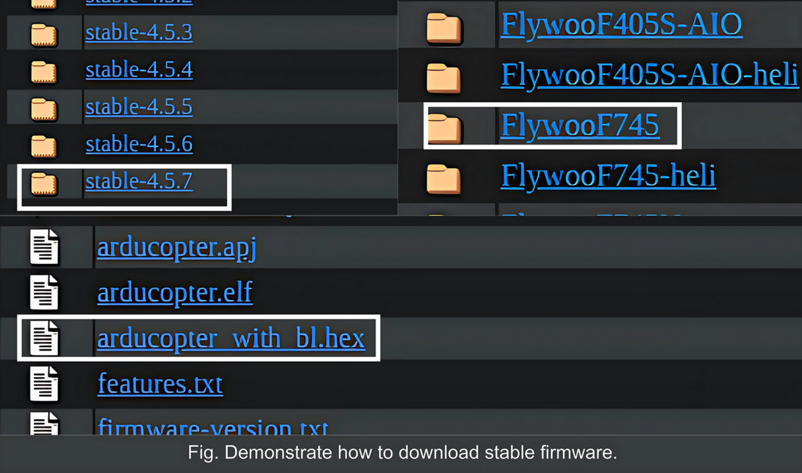
Download Firmware: Obtain any of the following file types:
.hex,.apj, or.elffrom the Ardupilot firmware repository or other sources.Ardupilot provides pre-built open-source binaries in
.hex,.elf, and.apjformats.Visit the latest stable version release page, select your flight controller, and download the binary file that matches your preferred boot method.
If you download
.hexor.elf, you will need to download the latest STM32 CUBE PROGRAMMER and follow the official documentation to set it up on your device.If you download the
.apjfile, download Mission Planner and follow the official documentation for installing the software on your device.
Step 4: Flash Firmware to Flight Controller
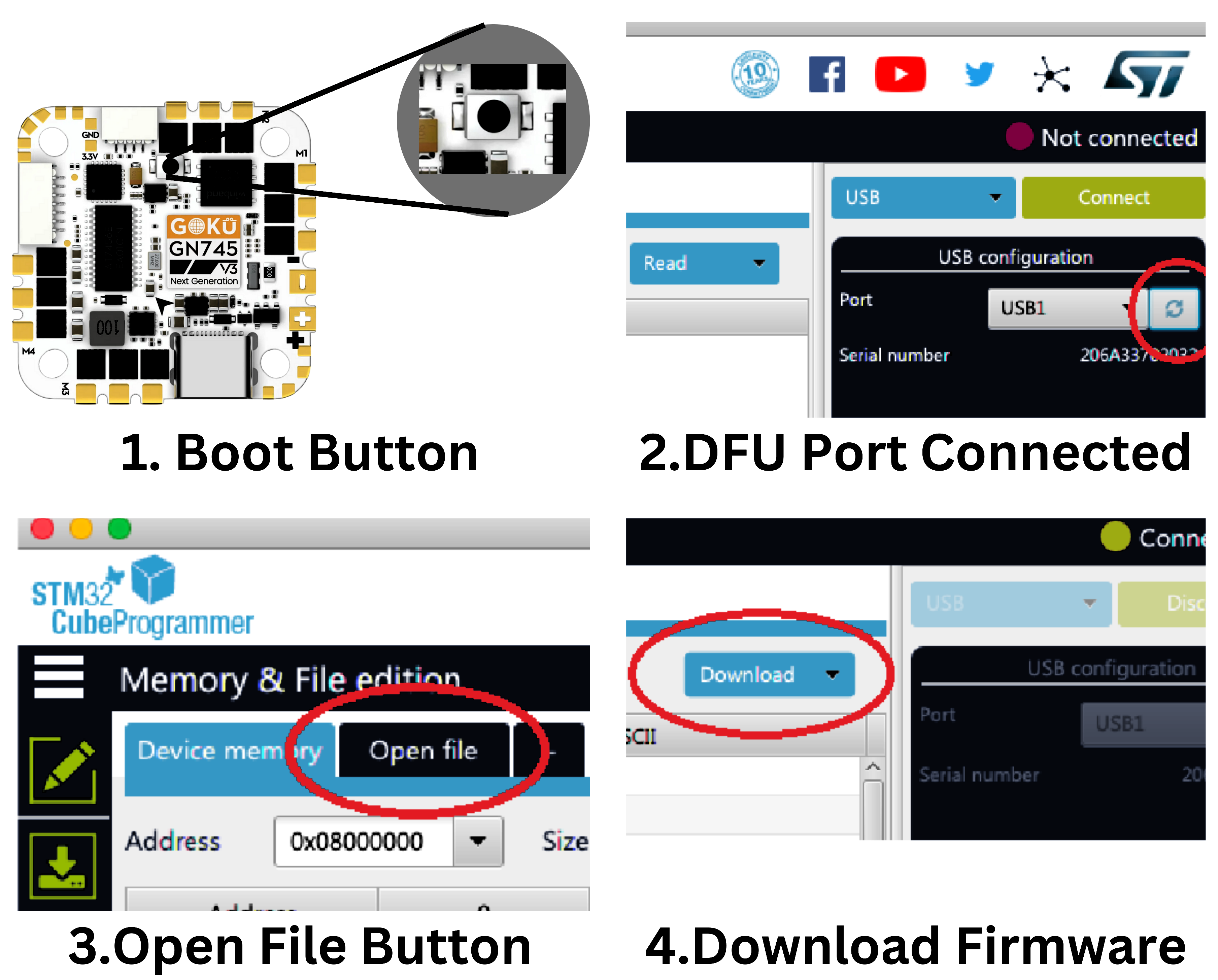
1. Cube Programmer (.hex or .elf)
After successful setup, open the application and follow the steps provided below.
Step 1: Keep the boot button pressed until the power cable is inserted into the PC/laptop.
Step 2: Open the Cube Programmer and select the USB option. You should see the PORT:USB1 in USB Configuration.
Note: If USB1 is not detected, repeat Step 1.Step 3: Press the connect button and open the `.hex` or `.elf` file.
Step 4: Press the Download button, wait for a successful download, and then remove the cable from the PC.
2. Mission Planner (.apj)
After successful setup, open the application and follow the steps provided below.
Step 1: Connect the data cable to your laptop/PC and check if you can see any COM port.
Step 2: Click on Initial Setup in the navigation bar, then select the Install Firmware option and click the Load custom firmware link.
Step 3: Select the `.apj` file and open it; this will automatically download the firmware.
If required, refer to Ardupilot for more details.
Step 5: Configure Parameters
Connect to Mission Planner:
- Open Mission Planner.
- Select the COM port at the top right corner and click Connect.
1. Set Param for Stable Firmware
- Select
Full Parameter List. - Click the Load From File option on the right side panel.
- use the swiftProStable.param downloaded from above.
- Upload the
swiftProStable.paramfile. - Click on
Write parameterand confirm with "OK" or "YES" for default parameters. - Note: Upload the files and write the parameter 3 times to ensure all the param are successfully set.
- press
Ctrl+Fand pressreboot Pixhawk.
2. Set Param for Custom Firmware
- Select
Full Parameter List. - Click the
Load From Fileoption on the right side panel. - use the swiftProCustom.param downloaded from above.
- Upload the
swiftProCustom.paramfile. - Click on
Write parameterand confirm with "OK" or "YES" for default parameters. - Note: Upload the files and write the parameter 3 times to ensure all the param are successfully set.
- press
Ctrl+Fand pressreboot Pixhawk.
Step 6: Calibrate & Test Drone
- Connect to Mission Planner:
- Open Mission Planner.
- Select the COM port at the top right corner and click Connect.
- Accelerometer Calibration
- Click the Setup Icon in the navigation bar.
- Select Accel Calibration from the left panel under Mandatory Hardware.
- Select Calibrate Accel to start the full 3-axis calibration.
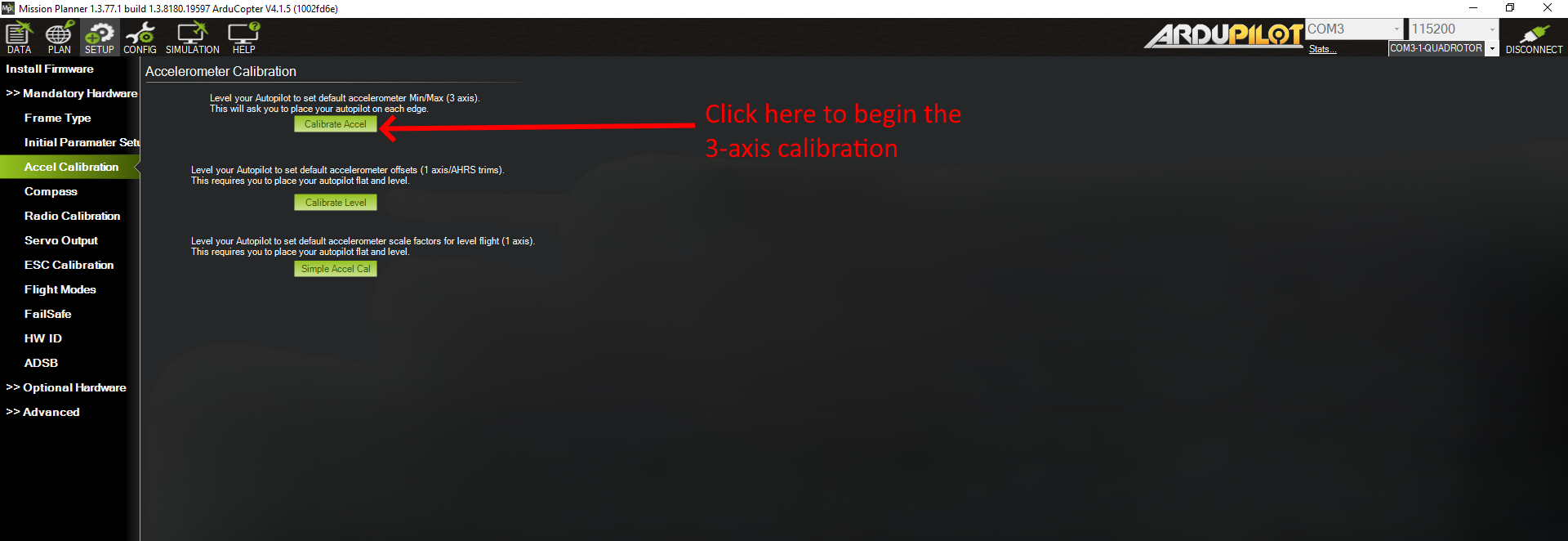
Mission Planner will prompt you to place the vehicle on each axis during calibration. Press any key to indicate that the autopilot is in position and then proceed to the next orientation.
The calibration positions are: level, right side, left side, nose down, nose up, and on its back.
Please click the Accelerometer Calibration for any queries.
Proceed through the required positions, using the Click when Done button once each position is reached and held still. When you have completed the calibration process, Mission Planner will display “Calibration Successful!” as shown below. 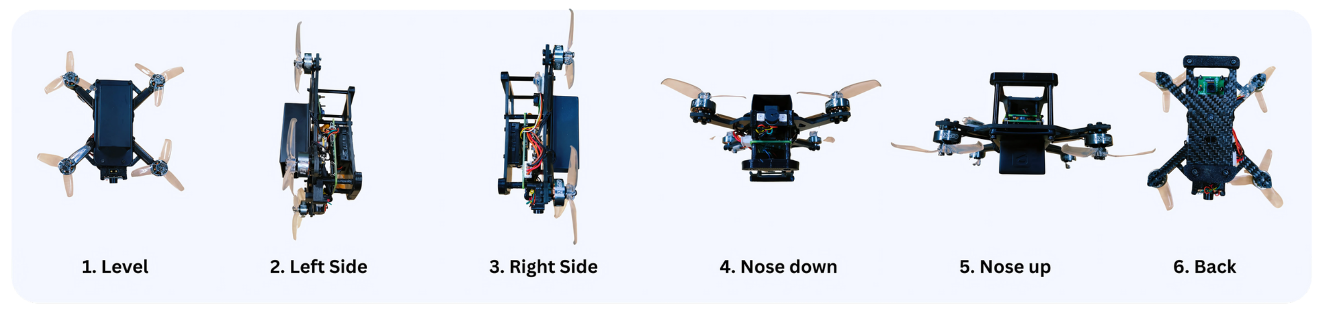
- The above image contain the top level images of swift Pro for Acceleration Calibration.
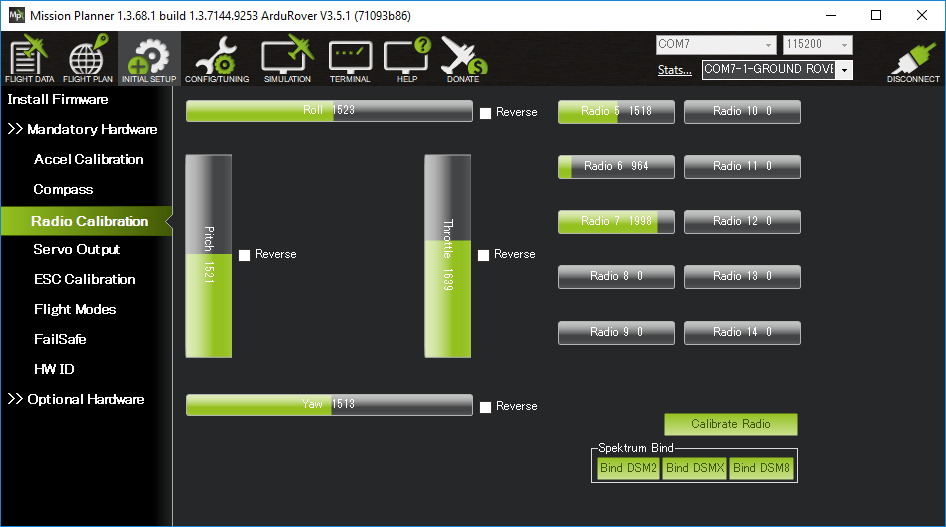
- Radio Calibration
- On your RadioMaster, select the Drone Model and ensure it is connected to the drone.
- Note: Ensure the battery is not connected.
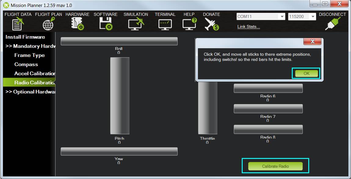
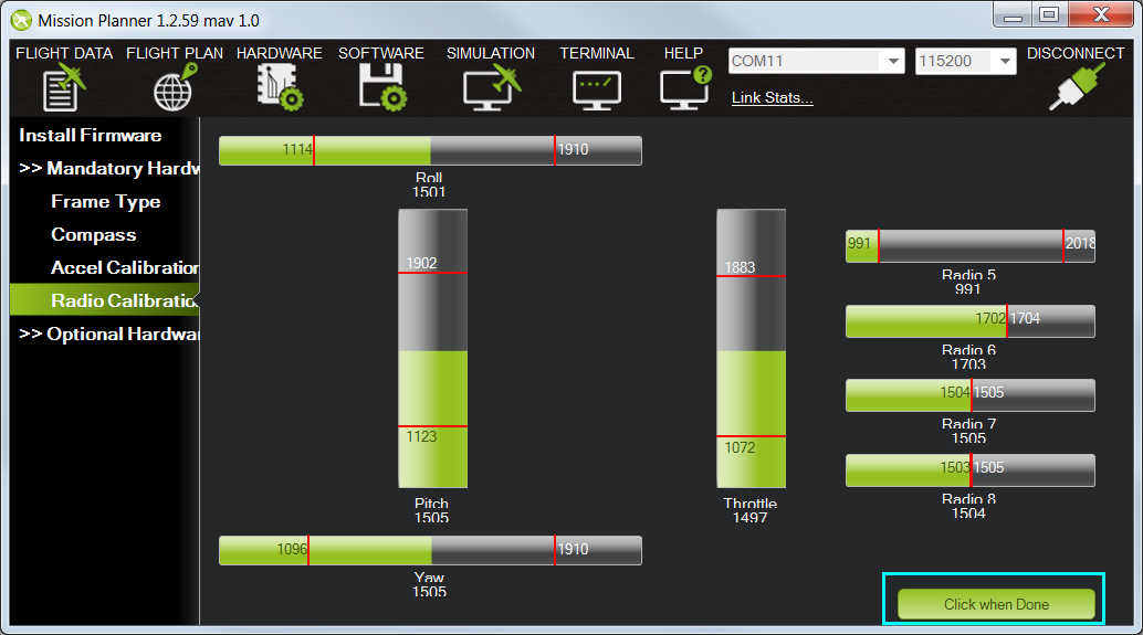
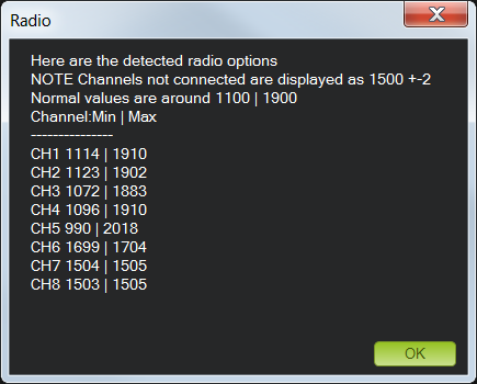
- Select Radio Calibration from the left panel under Mandatory Hardware.
- Move the controller stick; you should see the minimum and maximum levels of RC channels.
- Ensure it is increasing and decreasing according to the stick; otherwise, refer to the documentation.
- Flight Mode
- Select the
Flight Modesoption in Mandatory Hardware. - On your RadioMaster, there is a button labeled
SBon the top left corner with a tri-state output. 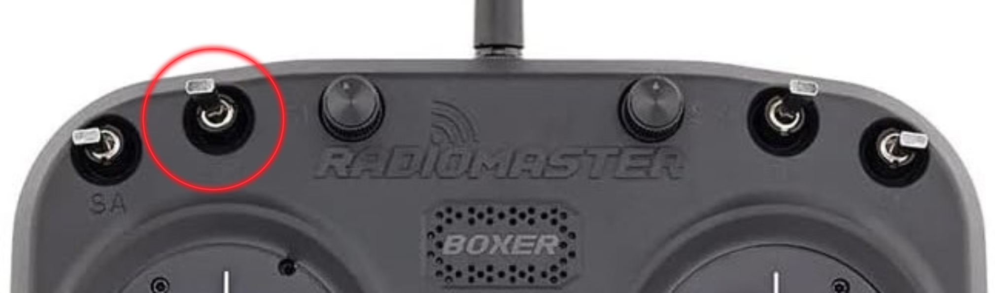
- You will see that when you switch the buttons, the mode highlighted in green in Mission Planner also changes.
- Select the appropriate mode or keep it default. The safest mode is
Stabilize.
- Select the
- Motor Test
- Note: Turn off the RC receiver and Remove the Propellers of drone to ensure safety.
- In Optional Hardware, open Motor Test.
- The diagram below explains the direction of the moter rotation.
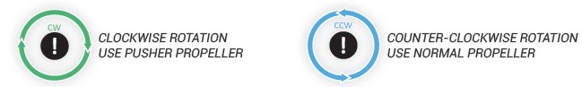
- The Drone Frame type is Betaflight X, so the rotation of the moters is shown below.
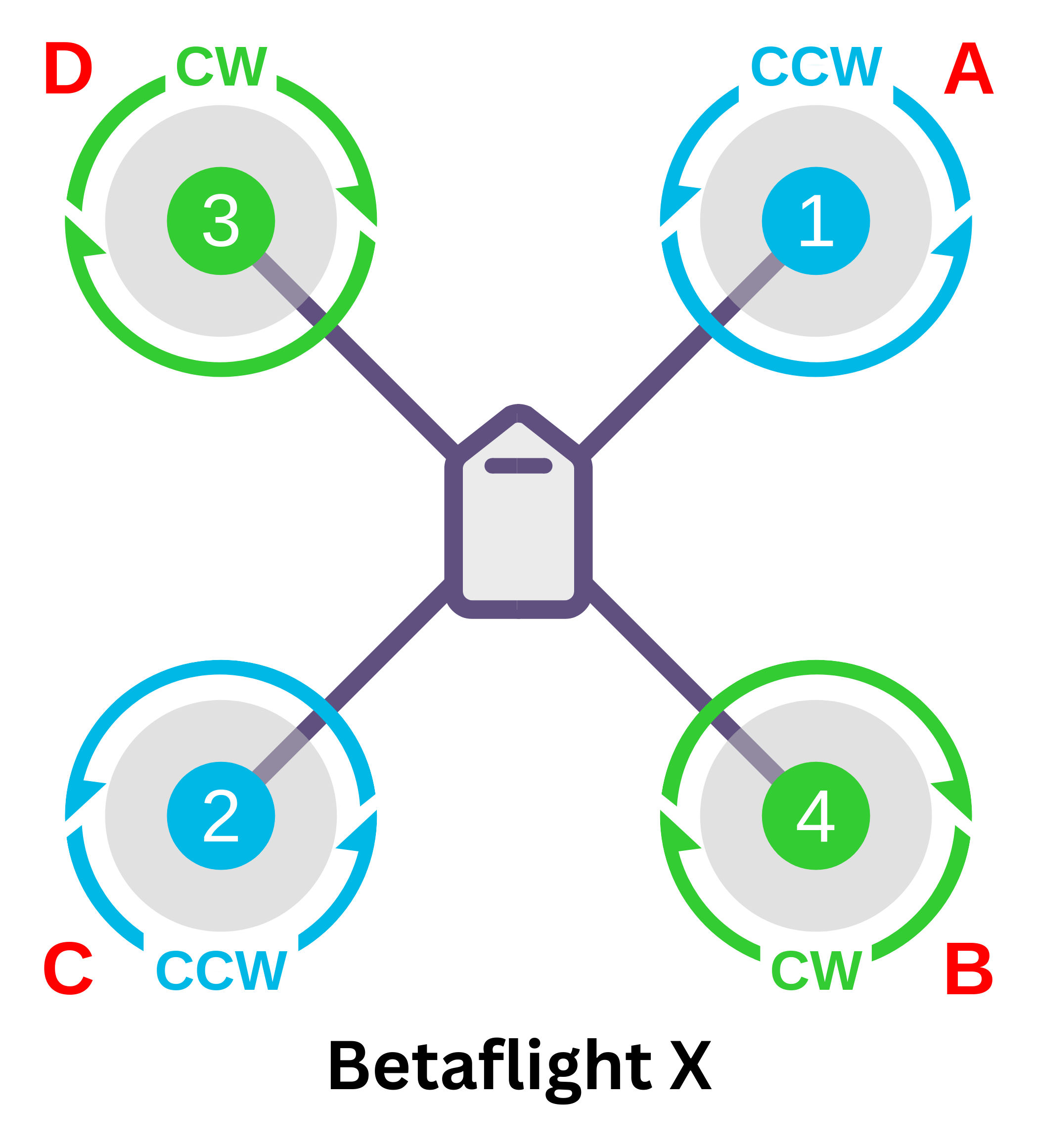
- Click the Test Motor option and ensure the direction mentioned in Mission Planner matches the direction shown in the above image.
Step 7: Rangefinder Data
- Go to the Data icon in the navigation bar.
- Click the right arrow and select the status icon as shown in the figure.
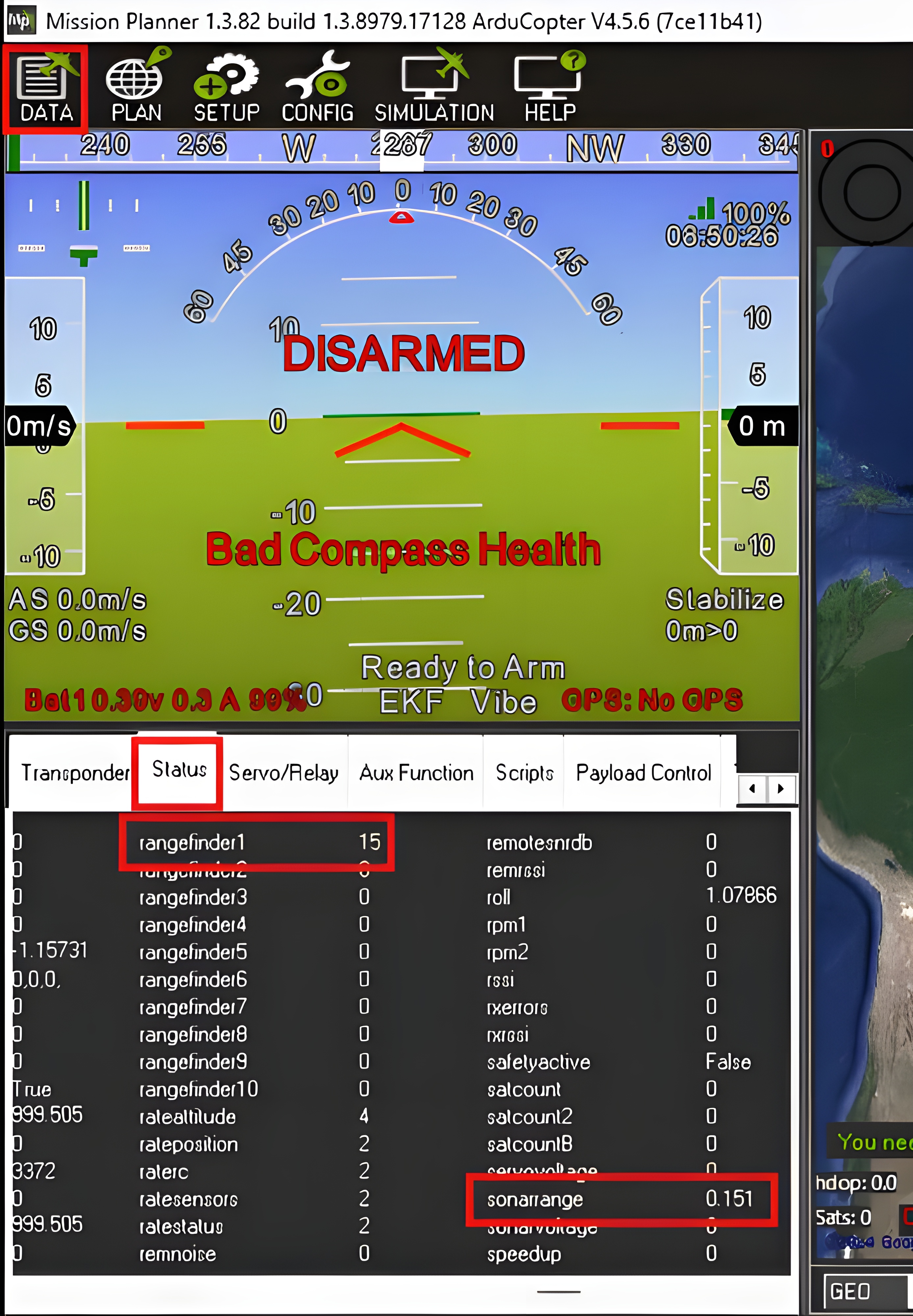
- Observe the
Rangefinder1value by lifting the drone to a certain height by hand. - Also, check if the
Sonarvalue changes when you move your drone.
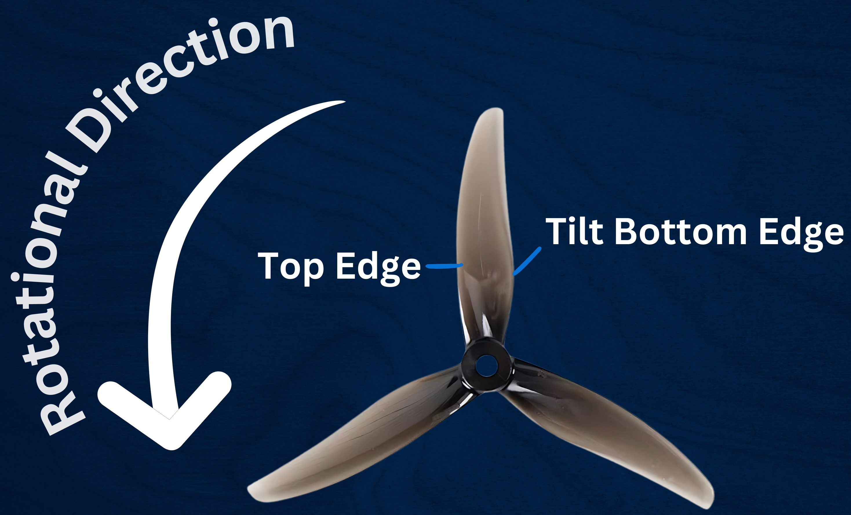
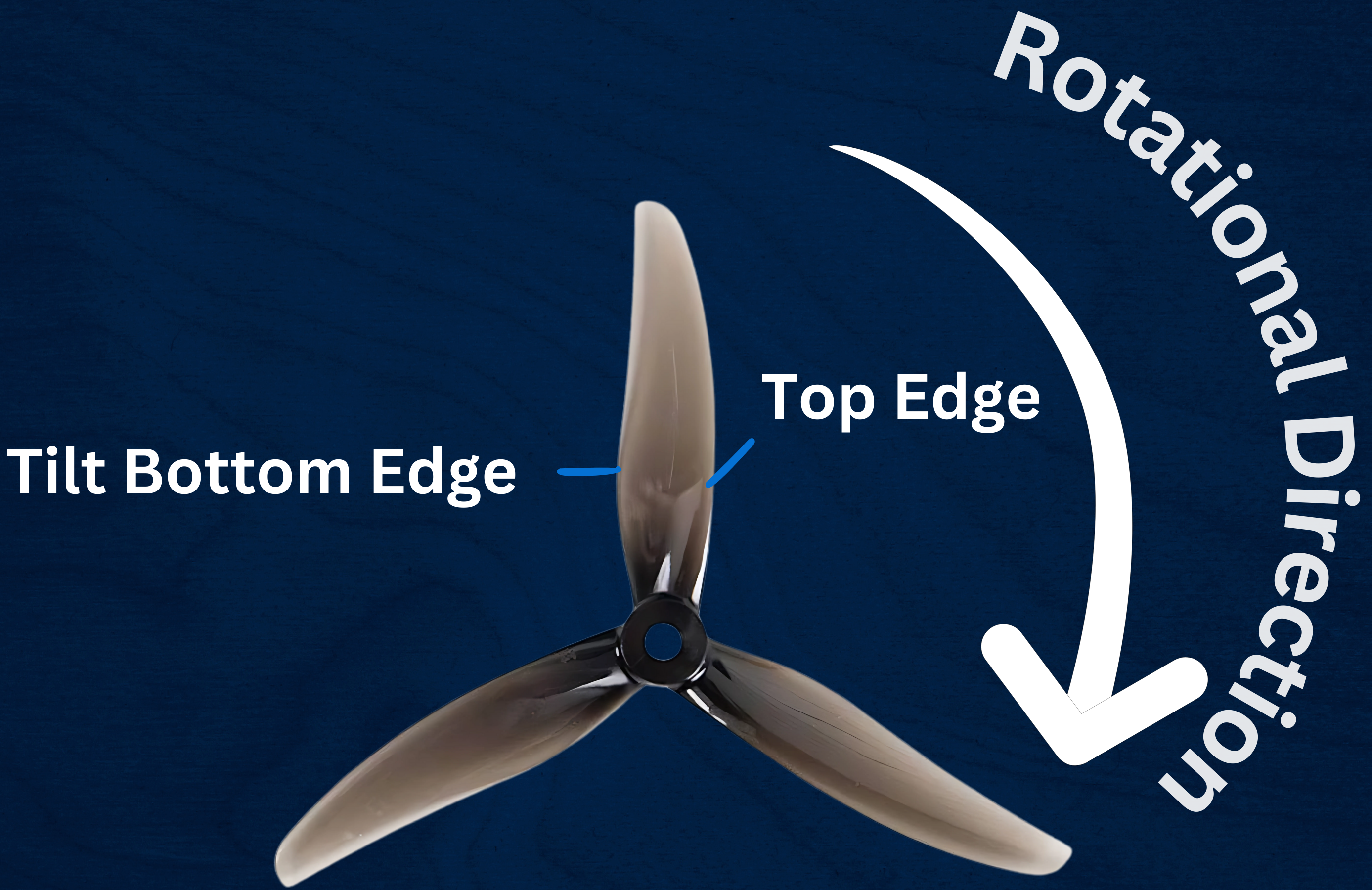
Step 8: Properllers Direction
- It is important to put the properllers in proper direction and side.
- To generate a thrust downward blades of properllers are tilted, the air forcefully goes downwards from top edge of properllers to tilted bottom edge.
- There is a High air pressure created below properllers and low pressure is created above the properllers, So there is a drag upwards.
By following this step you can successfully setup your Swift Pro.
Note: Always adhere to safety protocols during setup and testing to avoid any damage to your drone or potential injury.
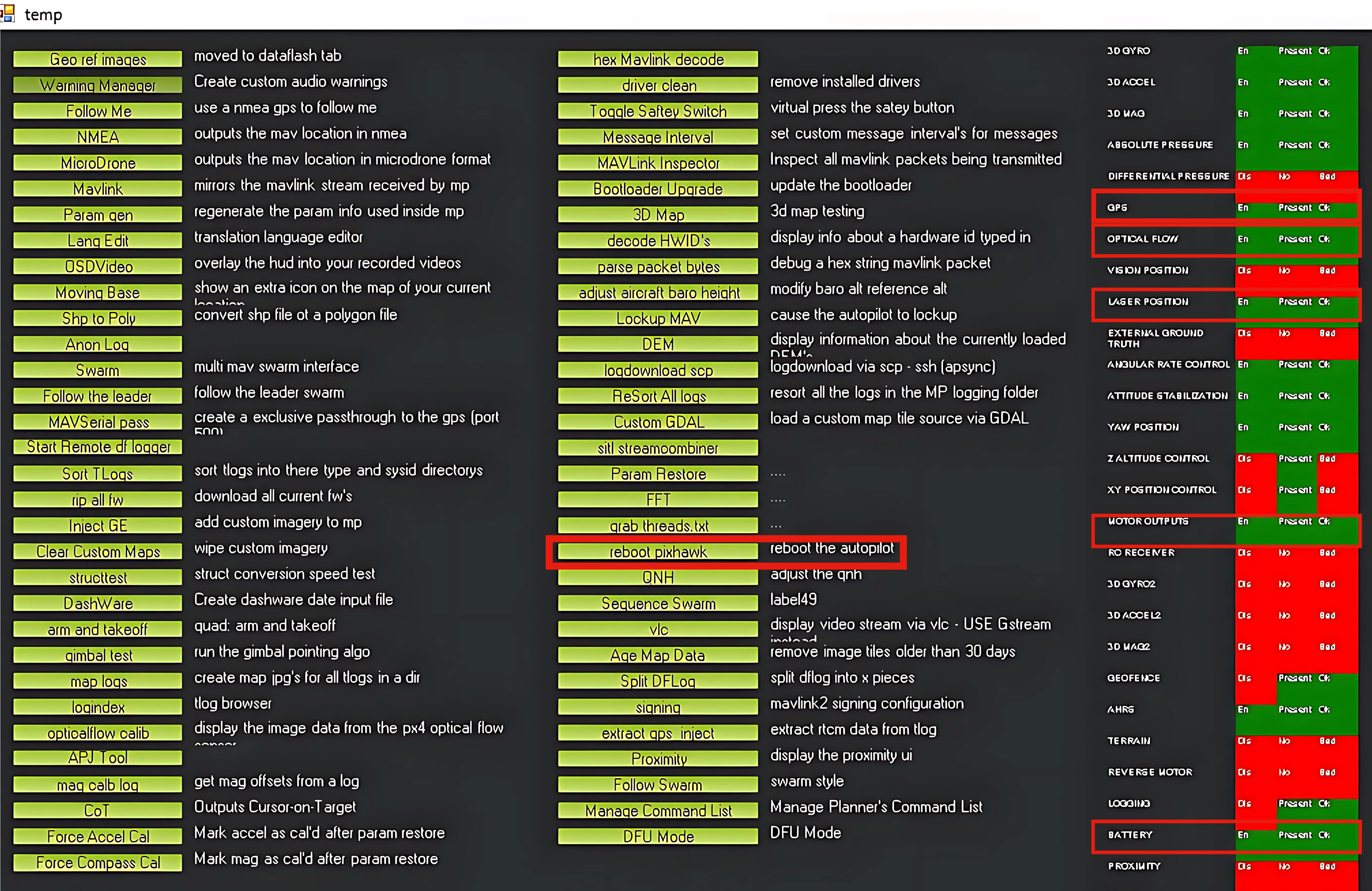
- You can also check all the sensors working correctly after connecting battery in Mission Planner.
- Press
Ctrl + Fin mission Planner. - Some Highlighted parts should be Ok and correct before the flight.
Let's understand the indepth parameter we set in our swiftPro.param list.
- Frame Shape
- This parameter defines the class and type, which helps the firmware set the basic dynamics according to the vehicle type and its frame.
- Go to
CONFIG-->Full parameter List-->FRAME FRAME_CLASSValue = 1 (Quad)FRAME_TYPEValue = 12 (BetaFlightX)
- Arming Checks
- This parameter helps to define safety modes for Arming of drone.
- Most of the big drone often has many safety checks, but in this drone since it is small we do not require any arming checks, so disable it.
- Go to
CONFIG-->Full parameter List-->ARMING ARMING_CHECKValue = 0 (No Arming Checks required)
- EK3 Sensor Fusion (Extended Kalman Filter)
- An Extended Kalman Filter (EKF) algorithm is used to estimate vehicle position, velocity and angular orientation based on rate gyroscopes, accelerometer, compass, GPS, airspeed and barometric pressure measurements.
- Go to
CONFIG-->Full parameter List-->EK3-->EK3_SRC1 EK3_SRC1_POSZValue = 2 (RangeFinder)EK3_SRC1_VELXYValue = 5 (Opticalflow)- EKF3 supports in-flight switching of sensors which can be useful for transitioning between GPS and Non-GPS environments. See GPS / Non-GPS Transitions for more details.
- Go to
CONFIG-->Full parameter List-->EK3-->EK3_SRC2 EK3_SRC1_POSZValue = 1 (Baro)
- Flight Mode Channel Selection
- The firmware need to know from which channel the different flight mode are switching. So in this case it is swiching from
Channel6. - Go to
CONFIG-->Full parameter List-->FLTMODE FLTMODE_CHValue = 6 (Channel6)
- Arming/Disarming
- Setting a button to arm/disarm.
- Go to
CONFIG-->Full parameter List-->RC5 RC5_OPTIONvalue = 153(ArmDisarm (4.2 and Higher)), it basically means firmware version 4.2.x and above.
- RangeFinder Settings
- This sensor is a replacement for GPS values of z-axis. The drone calculate its height using rangefinder sensor.
- Go to
CONFIG-->Full parameter List-->RNGFND1 RNGFND1_TYPEvalue = 16 (VL53L0X or VL53L1X)RNGFND1_ADDRvalue = 41 (It uses I2C protocol so we need o specify the address)RNGFND1_MAX_CMvalue = 120 (CM)RNGFND1_MIN_CMvalue = 5 (CM)RNGFND1_SCALINGvalue = 1 (m/V)
- Serial Ports
- Go to
SETUP-->Mandatory Hardware-->Serial Ports SERIAL PORT2 UART2Speed = 57600 and Protocol = RCIN.SERIAL PORT4 UART4Speed = 115200 and Protocol = OpticalFlow.SERIAL PORT6 UART6Speed = 57600 and Protocol = GPS- All others ports keep the protocol to None.
- Flight Modes
- Depending on the applications we use differnt flight modes.
- Go to
SETUP-->Mandatory Hardware-->Flight Modes Flight Mode 1Keep inStabilizemode.Flight Mode 4Keep inAltHOLDmode.Flight Mode 6Keep inPosHOLDmode.